After the great results achieved by the projects USB DAC2a and USB DAC 2b created in collaboration with Quanghao for the realization of the modules and the my friends Angelo and Sandro for the listening sessions to optimize the components and chose the best solutions, we had the idea of creating a new project based on the ES9018 chip.
The main characteristics of the ES9018 are the patented 32-bit Hyperstream™ DAC architecture and Time Domain Jitter Eliminator.
This is the first DAC chip that does not use the master clock on I2S bus and it automatically resample the input signal at the highest resolution available 32bit 384KHz.
 |
 |
 |
 |
The new DAC ES9018 module have these features:

- top performance linear pre-regulator
- separated fast shunt for any digital section
- separated fast shunt for any analog channel
- remote volume control
- remote mute control
- remote input control
- remap DAC to share I2S connection with DSD
- Amanero module integrated to have USB input and support 44,88,96,192,384KHz PCM and DSD
- On board reference 100MHz Crystek oscillator with a jitter of 0.5psec
- 3 spdif input: coax RCA, Toslink optical and AES/EBU
- passive I/V
- optional hi-end differential solid state op-amp


USB - I2S MODULE
I have tested these USB-I2S interfaces and I have found very big differences in the sound:
After 3 tests in 2 different rooms, 3 different systems, with 2 my friends I can affirm that XMOS and Amanero modules are the best.
The Amanero module sounds more open and detailed but also less solid and less smooth of XMOS module.
The XMOS module sometimes seems more confused but it also have a larger image of the acoustic scene.
The Amanero can play also 32bit 384KHz and DSD files (SACD format).

It is necessary set the Amonero module with the last firmware 1.58.
1) Download the update_tools and Unzip in a folder, for example on Desktop.
2) ERASE THE FLASH
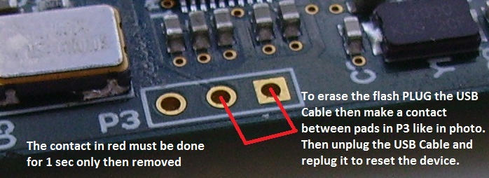
3) When you replug the erased device, Windows can ask about a driver.
4) Be sure to be connected to internet.
5) Run ConfigOEM109.exe and press download firmware.
6) When done close ConfigOEM109.exe and Unplug the USB Cable.
7) Replug the USB cable and if it's all ok the audio driver needs to detect the device.
8) Run again the ConfigOEM109.exe to map the channels

ES9018 DAC MODULE
The DAC module use a dedicated power supply with shunt separated for any section of the ES9018:
All the power supply use a controlled current source and a hi-speed shunt linear regulator.
This module the ES9018 when connected to the controller module can be configured to select 4 different inputs:
I have followed the configuration suggested on https://hifiduino.wordpress.com to share the same 3 wire for I2S and DSD.
The DAC input configuration is remapped by the Micontroller module setting the register #14.
Here the schematic modified from original to add the 3 spdif input and to show both mode in the same image.

The DAC module use a dedicated power supply with shunt separated for any section of the ES9018:
All the power supply use a controlled current source and a hi-speed shunt linear regulator.
This module the ES9018 when connected to the controller module can be configured to select 4 different inputs:
Using the controller module is also possible use the internal high performance volume of ES9018 with characteristics better than hi-end analog types (see article).
The default configuration of the ES9018 allow a single spdif input on DATA1 input pin.

|
 The ES9018 have 8 channel DAC that can be configure in parallel to get a stereo output and to increase the performances. The ES9018 DAC in theory can work with a voltage output or current output. Any DAC output have an internal 780ohm resistor to allow the parallel when it is used in voltage output mode. In stereo mode the internal resistor will be 780 / 4 = 195 ohm. Using the current mode should be necessary to use an external current to voltage stage (I/V). A good passive I/V can be created with a simple low value resistor. For the best performances use a single MK132 Caddock 10 - 18 ohm.
It is possible to use the voltage output and after some listening tests with my friends I consider this configuration as the best. In this case the output stage can be a transformer. The last firmware allow to get an un-balanced signal output but you get only 1Vrms at 0dB.
|


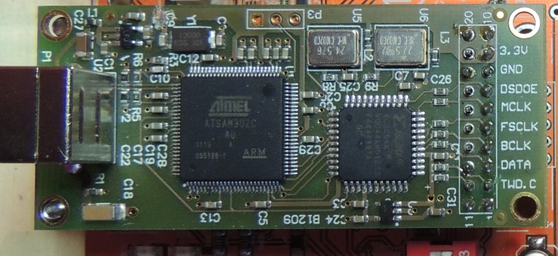
Here the photos of the very compact DAC section, top performances oscillator, shield and Amanero USB module.


OSCILLATOR

This is a critical component, the sound performances can be compromised with a cheap oscillator.

CONTROLLER MODULE SCHEMATIC

 |
|

CONTROLLER MODULE FIRMWARE
 |
To program the 16F877A Microchip microcontroller I have used the PICKIT 2 USB Development Programmer/Debugger (cod. PG164120 or DV164121) with a cost about 40-50$. |
I love the C language because it is very simple if compared to assembler.
 |
The my C source has been compiled with HI-TECH PICC-Lite™ Compiler V9.82 for PIC10/12/16 MCUs.
HI-TECH Software has provided a freeware HI-TECH PICC-Lite compiler as a tool for hobbyists and students, but the licence allows its use for commercial purposes as well. It is ideal as a teaching tool for an introduction into the 'C' language and embedded programing on a Microchip device. |
POWER SUPPLY

OUTPUT STAGE OPTION 1 - OP-AMP
The output voltage after the passive I/V is very low, about 100mVrms, so it is necessary an output stage with a good voltage gain.
Someone use a transformer to create a passive amplifier but in this case the frequency response is very compromised by the parasitic capacity of the transformer.
This output stage is used in Mark Levinson no. 380 and it is published on OPA627 datasheet like a High Speed Instrumentation Amplifier.
In the first stage the 100 ohm resistances can be connected to ground or not like the OP627 datasheet schematic and with this modification this stage sound much better.

I suggest OP627 on first stage and OPA2134 on second stage to get the best sound.
OUTPUT STAGE OPTION 2 - TUBES

|
The Raleigh Audio Line Stage clone is a Differential parafeed line stage push-pull with a pair of CCS (constant current source) to isolate the power supply from the signal. A 2.2uF parafeed capacitor isolating the output transformer from the power supply current so is possible to use little output transformers with amorphous core. I have used the LL1674 Lundahl transformer with a turn ratio 4+4 : 1+1 and a 2.2uF Z-Cap Supreme by Jantzen. It is necessary a not common vacuum tube for this output stage because we need high voltage gain and low internal resistance. The high voltage gain is necessary to convert the DAC output of about 100mVrms to 7Vrms because after it is reduced by the output transformer to 1.5Vrms It is necessary a transformer to reduce the output impedance and to create a differential signal.
The low internal resistance of the EC86 ensures a good low and high frequency response. To create this output stage I have used four K & K Audio Basic CCS modules with large heatsink. The Lundahl transformer with amorphous core ensure the highest level of transparency. Only 6 resistors are necessary for both the channels, for each I decided to use a parallel connection of two to reduce the parasitic inductance.
|

The power supply for this output stage could be a solid state like the following or a simple passive with choke.

OUTPUT STAGE OPTION 3 - TRANSFORMER
After many listening tests with my friends I consider this configuration as the best.
I don't suggest an I/V made with a transformer so use only 1:1 configuration with center 10K // 2.2 - 22uF Sanyo OS-CON as described in the old Glass Audio article of Stefano Perugini.
The LL1684 with the amorphous core is the best choice as output transformer.

CONFIGURE PLAYER
In order to play PCM and DSD audio tracks on Windows XP or 7 you can use Foobar2000 or JRiver Media Center.
The JRiver is more simple and with this configuration you can play 44,88,96,192,384KHz, DSD files and SACD ISO.


To use Foobar2000 is much more complex
You can follows the guide on: https://hifiduino.wordpress.com or this following images.
copy foo_input_sacd.dll, foo_dsd_asio.dll and foo_out_ks.dll in the directory C:\Program\foobar2000\components
If you select as output device the ASIO4ALL when you start to play any tracks an little icon will be insert in the Appl. Bar.

![]()
Quang Hao Dac – Bring Music To Life


