The No Oversampling DAC give a more natural sound but if you ear the TDA1541 and TDA1543 seem to lose details.
The AD1865N-K with passive I/V give a perfect combination, natural sound and all the details.
The AD1865N-K give the better performances with a 200ohm MK132 Caddock as passive I/V.
In this configuration the output signal is too low to drive any amplifier so I have design for the AD1865N-K the better output stage.
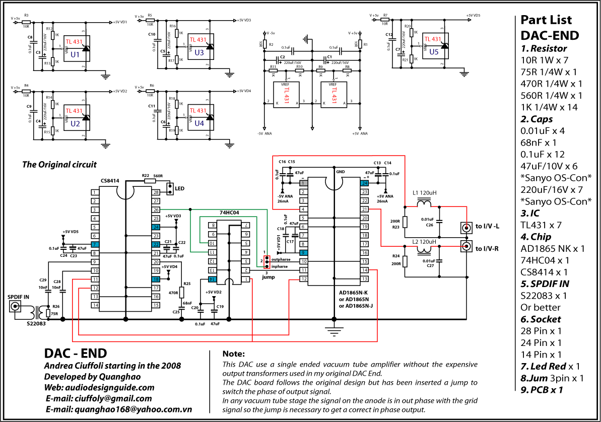
This DAC use a single ended vacuum tube amplifier without the expensive output transformers used in my original DAC End.
The DAC board follows the original design but has been inserted a jump to switch the phase of output signal.
In any vacuum tube stage the signal on the anode is in out phase with the grid signal so the jump is necessary to get a correct in phase output.
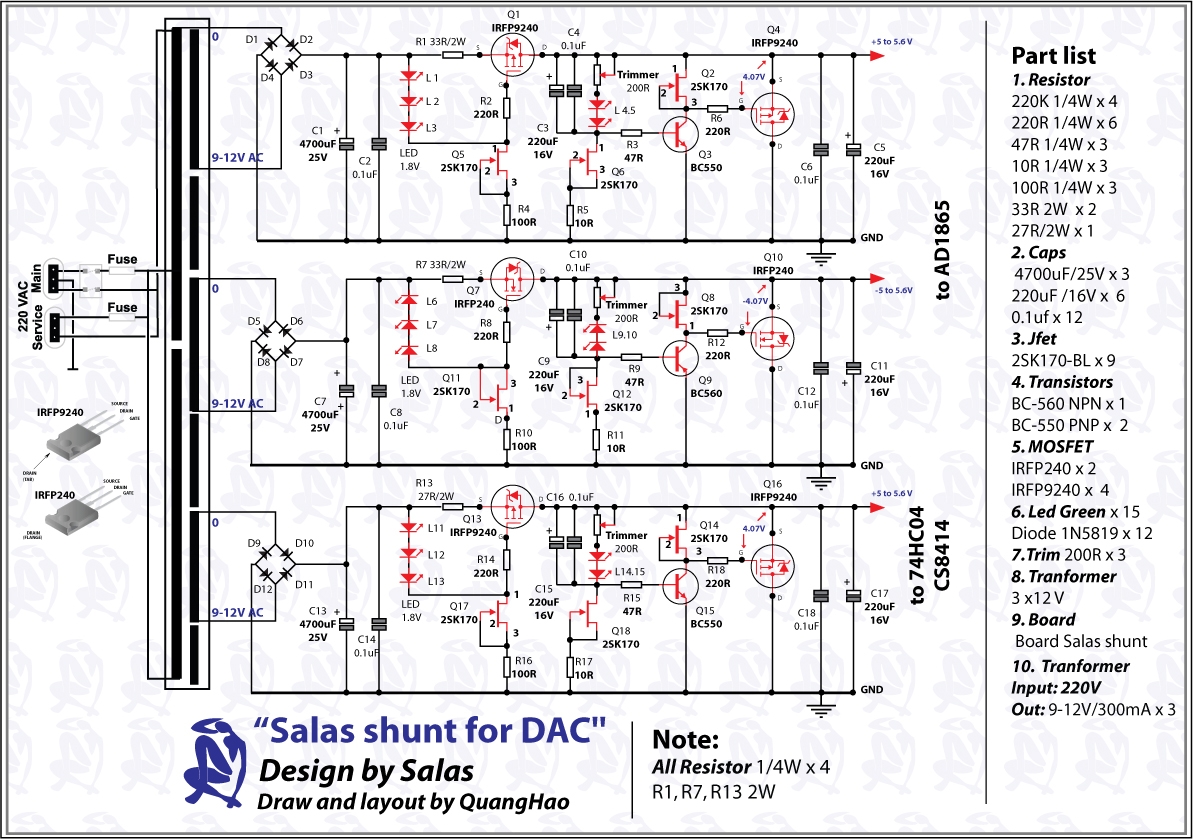
After some test has been decided to use shunt regulator to increase the sonic performances so a Salas regulator has been used for the DAC section.
Quang Hao have created a group buy on diyAudio to reduce the production cost of these pcb.
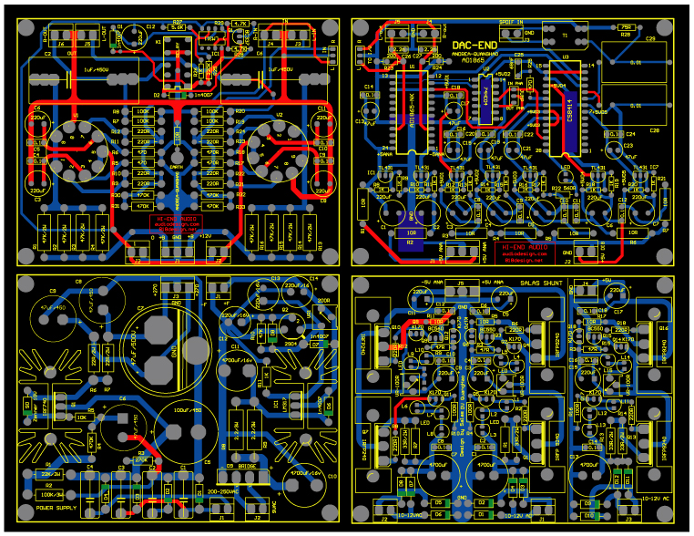
Any board have the same size 12.5 x 9.5 and all 19 x 25.
All these pcb boards has been created only for DIY so no commercial use is allowed.

COMPONENTS
About wire forget the teflon ! use only stranded tinned copper wire with pvc isulator.
A very good quality stranded tinned copper wire could be buy directly from E-Z-HOOK that carries an extensive line of fine stranded and extra flexible wire.
DAC BOARD
On the pcb layout is visible the jump for the digital phase inverter as described in the introduction and no other regulation are necessary.
A little post shunt regulators using the TL431 has been inserted to separate all the power supply like suggested in the datasheet of AD1865 and CS8414.
 |
 |
I suggest only a MK132 Caddock resistors like current to voltage converter (I/V) so the internal active I/V of AD1865 is not used.
In parallel to the 200-220ohm I/V resistors will be inserted a little capacitor necessary to create a high frequency cut-off upper.
The original DAC end have no capacitor on output because in this case this filter is created by the output transformers band.

POWER SUPPLY OF DAC BOARD
This schematic follows the Salas schematic.

OUTPUT STAGE
This output stage has been design to get an output impedance near to 1Kohm with only one vacuum tube on the signal path and without use output transformers.
The relay will short the output to ground during the switch on and switch off phase to prevent dc peak on the outputs.
The design and pcb is compatible with E182CC and 5687, in the first case the choice should be a NOS E182CC Mullard (not the new production) and for the 5687 the best is a NOS Jan Philips.
The E182CC will give an higher output level because the amplification factor is 24 instead of 17 and the internal resistance is quite the same.
Using the 5687 the voltage gain of this stage is 12.7x so the output at 0db is 127mV * 12.7 = 1.6Vrms and with the E182CC will be 127mV * 17.9 = 2.3Vrms.


POWER SUPPLY OF OUTPUT STAGE
The power supply for the vacuum tube stage is quite the same of original DAC End.
It use a no feedback regulator inspired to the Virtual Battery invented many years ago by Technics.
To get the best sonic performances I suggest to use a Jensen electrolytic on output but any other audio grade cap. will be good.
For the filaments has been used a slow turn power supply using a common LM317 to get a long life time of tubes.

MEASUREMENTS
I have used in some measurements the Clio system by Audiomatica with the Transit by M-Audio to use the USB port of my portable pc (instead of the PCI audio board).
Follow the measurement on the prototype of the output stage using the 5687 Jan Philips, distortion is less than 0.2% and the frequency response is flat on the 20-20KHz.


Here the measurements environment has been composed by a PC with EMU 0404 USB soundcard and ARTA software to get a frequency response until 100KHz.
Follows the measurement of the DAC board on AD1865 output without any filter, the sampling frequency 44KHz is at -35dB.

Follows in the same conditions the frequency response without sound card errors compensation

Follows the measurement of the DAC board on AD1865 output with a filter composed by a 10nF capacitor in parallel to the 200ohm resistor,
the sampling frequency 44KHz is at -35dB.
The high frequency cut-off is the result of this formula
Ft(-3db) = 1 / ( 2 * pi * R * C ) = 1 / ( 2 * 3.14 * 200 * 10E-9 ) = 79Khz

Follows in the same conditions the frequency response without sound card errors compensation

Follows the measurement of the DAC board on AD1865 output with a filter composed by a 0.033uF capacitor in parallel to the 200ohm resistor,
the sampling frequency 44KHz is at -40dB.
The high frequency cut-off is the result of this formula
Ft(-3db) = 1 / ( 2 * pi * R * C ) = 1 / ( 2 * 3.14 * 200 * 0.033E-6 ) = 24Khz

Follows in the same conditions the frequency response without sound card errors compensation

Follows the measurement of the DAC board on AD1865 output with a filter composed by a 100uH choke and 10nF capacitor in parallel to the 200ohm resistor (like the AudioNote DAC), the sampling frequency 44KHz is at -35dB.

Follows in the same conditions the frequency response without sound card errors compensation
PHOTO
Some photos sent by Quang Hao
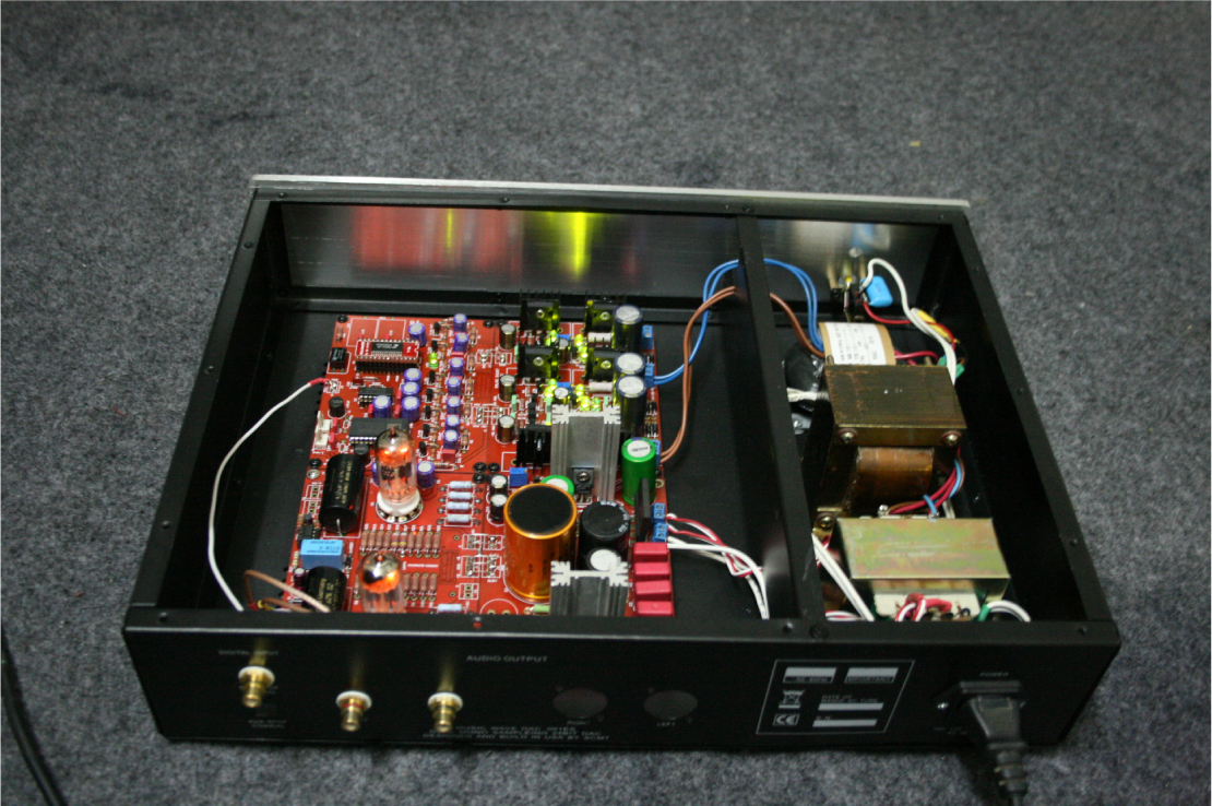


![]()
Quang Hao Dac – Bring Music To Life
